+91 9188248619
+91 9964784495
Proarch Self Supported
Roof Structures
Proarch roofing - the self-supported truss less arch shaped steel roofing technology for industrial roofs, is a name adding value to the Indian Building & Construction Industry. This innovation is an American expertise proven & applied in over 60 countries since the last 30 years. The self-supporting technology is the core element of Proarch Engineering, which differentiates it from traditional roofing concepts.and Proarch is the distributor for Proarch Engineering.
Its arch-shaped profile is uniquely designed, making the panel structurally strong to withstand loads as required by the relevant Building Codes. The panels fabricated are used for roofing that requires no trusses, purlins or ancillary supports for up to a single span of 36 meters. This makes the product the most ideal for large structures, where space optimization is vital. The flat panels can also be used for gable-end & side-wall cladding, in case of an all-steel building.
These roofing & cladding panels are manufactured from superior quality, structural grade steel using state-of-the-art, mobile panel fabrication equipment. This equipment can be transported to job-sites on all kinds of terrains, enabling fabrication & installation instantaneously. This nature of the process allows high-speed operations, bringing substantial benefits where time is a crucial factor. Precisely, the advantages of this new-age technology are many and favorable.
Salient Concept Features
- Self-supported structure without trusses, purlins or ancillary support, with unobstructed clear spans 6 meters to 36 meters.
- Provides larger enclosed volumes, free movement & effective handling of goods and higher flexibility in space utilization.
- Structure uses mechanical sealing and is free from holes, nuts, bolts, overlaps or sealants, ensures zero maintenance and also resistance to extreme weather conditions.
- Unique mechanical seaming for panel sealing ensures 100% leak-proof roofs.
- No bird nuisance and hence provides cleaner and more hygienic buildings.
- Innovative on-site fabrication and installation ensures an incredible installation speed of around 2000 sq. mtrs in 12 hrs, flexibility and enhanced efficiency with superior workmanship – faster project turnaround.
- Distinguishing arch shape and flexibility of colors result in strong aesthetic appeal
Application
- Manufacturing Facilities
- Food Processing Industry
- Engineering Units
- Pharmaceutical Industry
- Large-Scale Warehousing
- Defense Structures
- Air-Plane Hangars
- Agro-Warehousing
- Textile Units
- Sports Complex
- Conventional centers ,…..& many more
Basic Design and Technology
Proarch Roofings is designed to suit more than 20 different Building Codes from all around the world, of which, a few recognized ones are listed below:
- Indian Standards
- ASCE 7 – 1993, 1995 & 1998
- Standard Building Code 1997, 1999, 2000
- Uniform Building Code 1994, 1997
- British Standards
- Building Standard Law of Japan 1994
- International Building Code 2000
To carry out a calculative analysis of Proarch roofing, a special Design & Engineering software is used by the supplier(Proarch Engineering). This software factors the load parameters as per ASCE 7-02, International Building Code 2002 & BIS. Parameters like cyclone, earthquake, wind speed, live load etc. have been taken care of by design software provided by the technology provider where data has been fed as per prevailing IS standards in that region. The roof designs are made as per National Building Code after considering maximum wind speed in the respective Zone. There is a safety of 1.8 times, which is considered in the design. This gives adequate resistance against uplift force generated by wind gusts.
The analysis is carried out for the given span & center arch-rise, considering the required live load, wind load, dead load and the seismic factor. The analysis determines the thickness of steel and the arch reactions at the beam-level. This data is then incorporated by the Consulting Engineer in the design of building foundations, columns & beams. The number of fasteners / bolts per end of the panel is determined based on the uplift and shear capacities of the bolt and the steel. With the use of this exclusive Design & Engineering Software, a considerable amount of time and expense is saved in designing and selecting the most economical arch structure configuration. In a step-by-step, menu-driven procedure, the program modules will lead the designer through the analysis of the arch structure. Using our Design & Engineering software, an arch structure can be designed in about 5 minutes compared to conventional systems of design, which might have otherwise taken 2 to 3 weeks.
It is to be noted that the structural data drawn through this analysis shall be provided to the Consulting Engineer to design the required structure and assess its stability to withstand the loads arising out of the roof.
Fabrication and Installation Process
Raw Material
Proarch Roofings using PROFLEX SYSTEMS Technology uses high quality, high grade, 350 MPa YSt., Pre-Painted Galvalume Steel as the basic Raw material. The specifications of the same are detailed below.
| Base metal | Cold rolled structural quality steel in coil form |
| Steel grade | Grade D: 350 MPa YSt. Min. |
| Steel thickness | 0.70 mm To 1.64 mm (Base Metal Thickness) |
| Standard | ASTM A792, Steel Sheet, Aluminum-Zinc Alloy Coated by Hot-Dip Process |
| Bare Galvalume coating | AZ 150, 150 gms./sq. m. Alu-Zinc Coating (55% Al. & 45% Zn.) |
| Colour coating & testing methods | R.M.P., S.M.P., H.D.P. & P.V.D.F. Coatings. Top Side – Suitable for Roll-Forming, 20 microns total dry thickness, polyester on primer, NCCA II – 1 or ECCA T4 pencil hardness HB – 2H. NCCA Standard T-Bend Test method or ASTM D4 145-83 (no pick-off with scotch #610 tape). ECCA Test to 0.5T is also acceptable. Coating Test to ECCA T1 at every coil. Back Side – 12 microns total dry thickness, epoxy primer and polyester wash-coat. |
| Coil width | 914/ 605 mm, Tolerance: -0/ +0.02 mm |
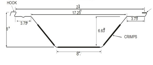
Basically, there is a roll-forming equipment, the TFP. This TFP equipment forms a profile having a finished width of 605 mm. Details of the panel design & dimensions are shown in the figure (1) below. The TFP roll-forming equipment basically has 2 sets of rollers. Once the desired material is fed, a straight panel of the required length is formed through the 1st set of rollers and cut by a guillotine shear blade. This straight panel is then fed into the 2nd set of rollers, which forms the horizontal & vertical stiffening members, giving the panel a curvature of the desired radius (as per the Design & Engineering of the Arch Configuration). These curved panels are then placed on the ground for further process. The profiling is done to the accuracy of a 2-4% tolerance in the Center Rise.
Figure 1 - (TFP Panel design & dimensions)
Profile Design
- This roll-forming equipment shall be placed inside the factory shop floor of a predetermined size for an efficient manufacturing and maneuvering of panels (this shall depend on the size of an individual panel & working area requirement). This equipment requires a flat, leveled and a solid-compacted surface so that it can be properly aligned. Hence the building contractor shall cooperate with Proarch roofings provider and their Project / Site Engineers.
- There will be a labor force of approximately 25-30 people involved in the manufacturing process, depending on the length & weight of the panel. This involves all the activities pertaining to the manufacturing of the TFP panels.
TFP Panel Interconnection Process
Once the panels are fabricated and placed on the ground, they are taken up for inter-connection with each other. These panels are placed on top of each other, sideways, so that they fit into their male-female formation.
Metal hooks / hangers to suspend light fixtures / cable trays / False ceilings / ducts / point loads, etc., will be placed at their (PRE-DETERMINED) locations before the panels are placed on top of each other. Each of these hooks / hangers has a load bearing capacity of approx. 50-75 kgs. point load (however, this shall depend on the final thickness of the material that has been chosen). It is mandatory for the lay-out to be predetermined and to be spelt out to Proarch ’ Engineers where such provisions are necessary. It would not be possible to provide such requirements once the profile is seamed.
The male-female formation is crimped together using mechanical seaming machines, which imposes a load of approximately 5 tons to ensure the seaming is of the required rigidity. These panels are connected in sets of 3 panels each, depending on the lifting capacity of the crane & other relevant factors. Each set of 3 panels is called a PICK. After seaming, a clear epoxy lacquer is applied on the inner side of the panel ends (6”-wide band). This forms a protective layer between the surface of panels and concrete beam to avoid direct contact and prevent any kind of damage to the material. This epoxy lacquer will also be provided at the cut edges before erection to ensure added protection against corrosion.
Visuals of ‘Before & After’ seaming the panels and the provision of hooks / hangers are shown in the figure (2) below. Also, the drawing of the hangers with its dimensions is shown in figure (3) below. For this operation, 4-6 skilled labor-team members are required.
Figure 2 - (TFP Panel interconnection)
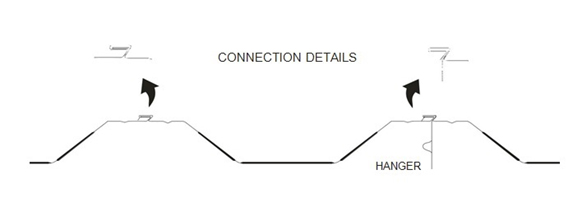
Figure 3 - Hooks / Hangers for Electrical Fixtures / Other Loads
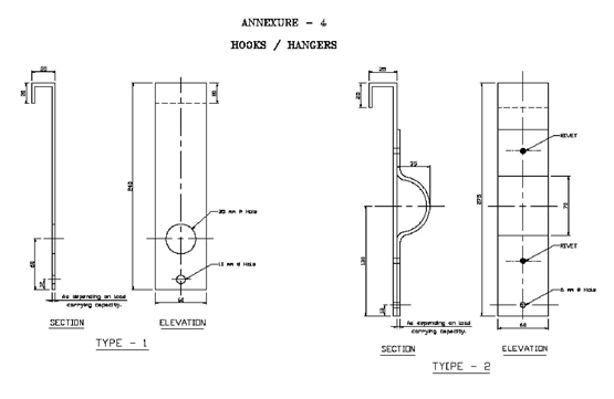
Figure 4 - Conceptual Gutter-Beam design
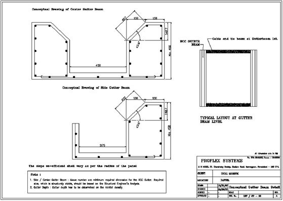
The RCC substructure has to be designed considering the arch reaction data & load combinations given by Proarch roofing. It shall be within the purview of the clients Consulting Engineer to ensure the structure is designed to cater to the adverse load conditions.
Installation Process
Proarch Roofing Profile, the TFP, is installed over concrete gutter-beams. The conceptual design / drawing of the required RCC gutter-beams are shown in figure (4)
Accessories
Accessories like ventilators and skylights can be provided with Proarch Engineering Roofing at the crown/ridge only by making cutouts in the Proflex panel. Cut out can be provided at every 20th panel (i.e. 20ft) incase of OFP and 10th panel (i.e. 20 ft) incase of TFP in the longitudinal direction of the building.
The size of the ventilator is 24” diameter and its capacity is 2200 CFM. As thumb rule calculations, you can provide one ventilator for every 100 Sq. mtrs area.
Skylights are of 2 mm polycarbonate or FRP material. 2’ x 7’ is std., but can be offered in other sizes.
Hangers for lighting requirements can also be provided.
The maximum load that we can hang from the roof is between 10-15 kg UDL per sq. meter. (uniformly distributed load) The maximum point load that we can hang is between 60-70 kgs but would vary and depend on the location at the roof and its end application. But this needs to be informed before material selection so this criterion can be taken into design consideration. Besides it is equally important to have a layout for hanging points in order to confirm the loading with respect to client’s end application requirements.
Proarch Engineering will provide and ensure the following
The line, level and the alignment of the same along the entire length of the beam will be checked by the Engineer after the concreting. No plaster on the slope of the beam will be allowed. Contractor will be given the guidance by the system provider to ensure the work is as required. In case of any flaw, the Consulting Engineers office should be referred for the ways the rectification is to be carried out.
Before erection, a Hammer test of the concrete will be carried out to ensure that the anchor bolts could be securely fixed on the support.
The scheme of Roll Forming, Fabrication and Seaming on the ground will be finalized by Proarch with respect to their operation, storing of raw materials, movement of cranes, assembly of the panels, etc.
The installation process has to be carried out from inside the building from the shop floor. In this case, a hard-compacted & leveled floor is required, where the crane shall be placed & moved along the length of the building as the installation is carried out. The installation shall start from one end of the building in one bay, and moving along the length of the building, the process shall be completed. The second bay shall be completed by following the same process.
Each PICK of panels will be lifted with the crane using a spreader bar and a sling evenly placed to ensure no distortion of the panel takes place during lifting and placing. The crane shall hold / support the PICK of panels till the alignment is done and completed using a plumb & a water tube, and is bolted into the beam. To ensure these panels don’t shift from their alignment, they shall be tied up with a guy rope to hold them in place. They will be supported with this rope till enough panels are installed to form a square, i.e., till the length and span are of an equal dimension.
The junction of the panels to the gutter beam shall be made using either 2-3 anchor bolts of the desired size on each end of the panel (depending on the stability requirement as derived from the Design calculations). GI anchor Bolts of required sizes and type, with 2.5 inches G.I vicer & neoprene washers would be provided as determined by the analysis during Design.
The installation process shall not be carried out in case of unfavorable weather conditions like rain and / or in case when the wind-speed is higher than 28 km/hour.
After all the panels are in place and installed, the same epoxy lacquer is applied at the junction of the panels to the beam where it has been bolted to form a protective layer on the bolts and the holes underneath.
After installation of the TFP panels, because of the profile design, trapezoidal voids are created between the gutter-beam and the panel corrugation. These voids will then be covered by a flashing, fabricated from the same sheeting material, or brick mortar. These voids shall be covered to make the system water-tight. This shall be done by the CLIENT or their appointed agencies.
Post-Installation Maintenance
Life of the roof depends on the substructure. However, based on the raw material that we use i.e. Galvalume, we can estimate a life span of 35-40 years for the roof. Internationally, such roofs are in existence for the last 25 years.
Normally there is no maintenance required except for when there is a hole punctured in the panel. In such a case, the damage can be rectified by patching up that area with similar material using rivets and appropriate silicone sealants & adhesives. This is a simple and quick process to make the system full-proof again.
For preventive maintenance, it is advised that at every 6-8 month intervals, the roof be washed with water to get rid of the dust or foreign particulars that may have accumulated during the period of time. Clearing of dust would prevent it from affecting the color-coat for a longer period of time.
Secondly, it should be ensured that the side gutters and the valley gutters are cleaned regularly to prevent them from clogging and thereby avoid any water from overflowing into the building.